AnasSarkiz/ble-pedometer
This code defines and configures various electronic hardware components such as surface-mount resistors, crystals, diodes, transistors, connectors, and switches with their physical footprints, schematic symbols, and 3D CAD models for PCB assembly.
- Version
- 1.0.7
- License
- unset
- Stars
- 0
CHARGER_BRINGUP.md
# BQ25186 / TPS7A02 power-tree bring-up

This is a firmware/bench specification, not supplied or tested firmware. Battery charging is not qualified by a clean PCB DRC result.

## Hardware defaults

- U2 is BQ25186DLHR, I²C address 0x6A, not BQ25150 at 0x6B.
- U6 provides nominal 3.3 V without any charger-register write. VSYS_RAW is the higher-voltage power-path rail; never connect it to MCU/accelerometer supply pins.
- R6 is now a 100 kΩ pull-up on CHG_CE_N, connected to DIO3. High disables charging. Hold it high during initialization and after any validation failure. There can be a short power-up interval before SYS_VDD rises; the charger's reset current is 10 mA.
- The battery must be protected, correctly polarized and have a qualified 10 kΩ NTC curve. TS/MR shares the NTC node with the wake button. A button press can suspend charging through the temperature/reset logic.
- There is no hardware IMAX resistor on this charger. A firmware error can select an excessive current. Validate and read back every relevant setting before driving CE low.

## Conservative initialization

With CE high, probe the charger, read its device identification/status, and reject unexpected or unreadable values. For a qualified 4.2 V cell, preserve PG status mode and set VBAT_CTRL (0x03) to 0x46. Select 10 mA initially: ICHG_CTRL (0x04) = 0x85 while software charging is disabled. After verifying settings, 0x05 keeps that current and clears software disable. For a cell explicitly qualified for 50 mA, the corresponding bytes are 0xA0 / 0x20. Never choose a current merely from the chip's 1 A capability.

Set the input limit to 100 mA while preserving other timer fields: update only bits 2:0 of TMR_ILIM (0x08) to 001. Program TS_CONTROL (0x0B) for the pack's approved range; 0xC0 selects cold 0°C, hot 45°C, warm 45°C and cool 10°C, subject to thermistor/threshold accuracy and pack qualification. Separately keep IC_CTRL (0x07) bit 7, TS_EN, set: this enables automatic temperature-based charge control. Monitoring alone does not establish that charging will be inhibited. Preserve other protection behavior, verify the watchdog/safety-timer policy, and read back all writes.

Enable charging only after confirming valid temperature, battery voltage, supply and readback. Supervise the watchdog and faults; do not leave firmware silently continuing after an I²C error. On MCU reset CE returns high. On charger reset the MCU must revalidate before restarting charging. Ship mode disconnects the system: it is not the normal pedometer sleep state. Normal operation uses MCU standby while the charger remains in battery-only operation.

## Bench sequence

1. Inspect continuity/shorts with no cell connected.
2. Use a current-limited battery simulator and confirm SYS_VDD, VDDR, reset, CE-high and display-off states.
3. Connect SWD; install firmware that leaves charging disabled.
4. Apply current-limited 5 V USB and verify the raw and regulated rails independently.
5. Exercise charge control first with suitable battery-emulation equipment; measure 10 mA, then the qualified current. Test disabled-charge leakage, unplug/replug and MCU reset.
6. Sweep an NTC simulator through normal, cold, hot, open and short conditions. Verify charging inhibits and recovers according to policy.
7. Validate fuel-gauge signed current, power-path handover, termination and watchdog behavior before using a real pack.
8. Qualify a real protected pack under supervision, including thermal measurements and display/radio load transients.

Register references: [TI BQ25186 datasheet](https://www.ti.com/lit/ds/symlink/bq25186.pdf), §6.5.1.4–6.5.1.12. These register bytes are design inputs requiring firmware tests and measured bench validation, not a safety certification.
Related Packages
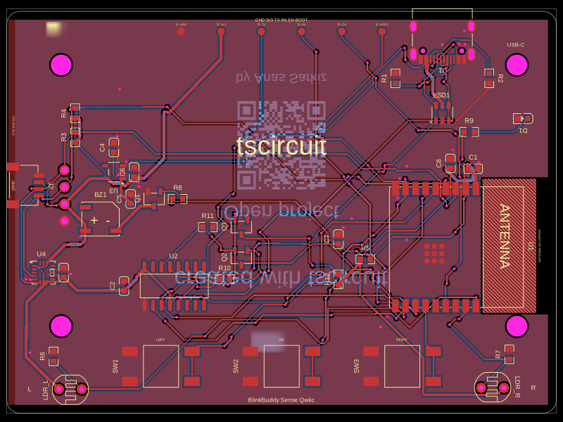 More from this authorAnasSarkiz/BlinkBuddyThis code defines and renders a 24mm square PCB silkscreen with a centered QR code graphic and labeling for open project instructions.
 Similar packagemohan-bee/speakerThis code defines configurable 3D models and PCB footprints for various electronic components, including a battery charger IC, a dual Hall sensor, a dual power switch, and a voltage regulator, with detailed pinouts, footprints, and CAD models for schematic and physical design.
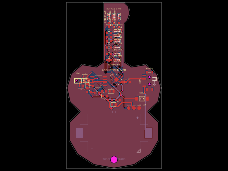 Discover something newgokul/acoustic-guitar-tunerThis code defines a miniature circuit board featuring a microcontroller (ATTINY1616-MNR), audio and power components, tactile switch, various LEDs, and passive components arranged with specific footprints, connections, and mechanical markings for a mini acoustic guitar tuner.