MustafaMulla29/wireless-mouse-pcb
This code defines a 3.3V low dropout voltage regulator chip (AP2112K-3.3TRG1) with five pins (VIN, GND, Enable, NC, VOUT) and its associated PCB footprint and 3D models for hardware implementation.
- Version
- 1.0.6
- License
- unset
- Stars
- 0
index.circuit.tsx
PCB
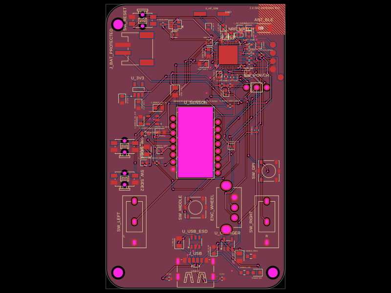
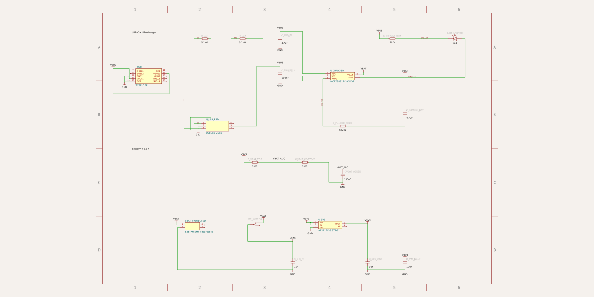
Schematic
import { BatteryPowerSection } from "./sections/BatteryPowerSection";
import { MouseInputsSection } from "./sections/MouseInputsSection";
import { OpticalSensorSection } from "./sections/OpticalSensorSection";
import { StatusAndDebugSection } from "./sections/StatusAndDebugSection";
import { UsbChargingSection } from "./sections/UsbChargingSection";
import { WirelessControllerSection } from "./sections/WirelessControllerSection";

export default () => (
  <board
    title="nRF52810 Bluetooth LE Wireless Mouse"
    width="44mm"
    height="70mm"
    borderRadius="5mm"
    layers={2}
    minViaHoleDiameter="0.3mm"
    minViaPadDiameter="0.45mm"
  >
    <schematicsheet
      name="power"
      displayName="Power, USB-C and LiPo Charging"
      sheetIndex={0}
    >
      <schematicsection
        name="UsbCharging"
        displayName="USB-C + LiPo Charger"
      />
      <schematicsection
        name="BatteryPower"
        displayName="Battery + 3.3 V"
      />
    </schematicsheet>

    <schematicsheet
      name="controller"
      displayName="Wireless Controller and Debug"
      sheetIndex={1}
    >
      <schematicsection
        name="WirelessController"
        displayName="nRF52810 + Clocks"
      />
      <schematicsection
        name="RadioFrontEnd"
        displayName="2.4 GHz Radio"
      />
      <schematicsection
        name="StatusDebug"
        displayName="Debug LED + SWD"
      />
    </schematicsheet>

    <schematicsheet
      name="sensor"
      displayName="Optical Motion Sensor"
      sheetIndex={2}
    >
      <schematicsection
        name="OpticalSensor"
        displayName="Optical Sensor"
      />
    </schematicsheet>

    <schematicsheet
      name="inputs"
      displayName="Mouse Buttons and Scroll Wheel"
      sheetIndex={3}
    >
      <schematicsection name="MouseInputs" displayName="Buttons + Wheel" />
    </schematicsheet>

    <UsbChargingSection />
    <BatteryPowerSection />
    <WirelessControllerSection />
    <StatusAndDebugSection />
    <OpticalSensorSection />
    <MouseInputsSection />

    <hole name="MH_REAR_LEFT" diameter="2.4mm" pcbX={-19} pcbY={30} />
    <hole name="MH_FRONT_LEFT" diameter="2.4mm" pcbX={-19} pcbY={-31} />
    <hole name="MH_FRONT_RIGHT" diameter="2.4mm" pcbX={19} pcbY={-31} />
    <keepout
      shape="rect"
      width="6.5mm"
      height="7.5mm"
      pcbX={18.75}
      pcbY={31.25}
      layers={["top"]}
      excludeRefs={[".ANT_BLE"]}
    />
    <keepout
      shape="rect"
      width="6.5mm"
      height="7.5mm"
      pcbX={18.75}
      pcbY={31.25}
      layers={["bottom"]}
      excludeRefs={[".ANT_BLE"]}
    />

    <copperpour
      name="GND_TOP"
      connectsTo="net.GND"
      layer="top"
      clearance="0.2mm"
      boardEdgeMargin="0.3mm"
      cutoutMargin="0.5mm"
    />
    <copperpour
      name="GND_BOTTOM"
      connectsTo="net.GND"
      layer="bottom"
      clearance="0.2mm"
      boardEdgeMargin="0.3mm"
      cutoutMargin="0.5mm"
    />

    <silkscreentext
      text="2.4 GHz ANTENNA K/O"
      fontSize="0.65mm"
      pcbX={17}
      pcbY={34}
    />
    <silkscreentext
      text="SENSOR CUTOUT - LM19-LSI - Z=2.4mm"
      fontSize="0.55mm"
      pcbX={0}
      pcbY={11.2}
    />
    <silkscreentext text="USB-C" fontSize="0.65mm" pcbX={0} pcbY={-30.7} />
    <silkscreentext text="L" fontSize="0.8mm" pcbX={-17.5} pcbY={-22} />
    <silkscreentext text="R" fontSize="0.8mm" pcbX={17.5} pcbY={-22} />
    <silkscreentext text="SWD" fontSize="0.65mm" pcbX={8} pcbY={33} />
  </board>
);
Related Packages
 More from this authorMustafaMulla29/MSPM0G3507-tsxThe code defines a 64-pin QFP package of the Texas Instruments MSPM0G3507 ARM Cortex-M0+ microcontroller, detailing its pinout, electrical connections, and external support components such as decoupling capacitors, resistors, and headers for power management, debugging, and I/O functions.
 Similar packagemohan-bee/speakerThis code defines configurable 3D models and PCB footprints for various electronic components, including a battery charger IC, a dual Hall sensor, a dual power switch, and a voltage regulator, with detailed pinouts, footprints, and CAD models for schematic and physical design.
 Discover something newrushabhcodes/ESP32-E-ReaderThis code defines the physical layout and schematic wiring of an ESP32-based e-reader device, including various surface-mount components such as connectors, ICs, resistors, capacitors, inductors, diodes, pushbuttons, and an antenna, with precise PCB placement and interconnection details.